How to Adjust Water Differential Pressure Switch
How to calibrate and adjust differential pressure switch, which differential pressure controller is convenient for installation and debugging
Like a pressure switch, a differential pressure switch can be calibrated to a known set point. You can calibrate the differential pressure switch as quickly as you can calibrate the pressure switch. However, some modifications have been made to the process in order to calibrate it more accurately.
Digital Differential Pressure Switches with 2 set points
No need calibrate, easy adjust by Pressing Button Key, Made by A.YITE TECH
Quick calibration procedure for differential pressure switches
Equipment required includes:
(a) variable stressors
(b) digital multimeters or continuity test lamps
(c) tester
The calibration Step:
Step 1
Connect the variable pressure source to the test table and the hi-side pressure port of the switch.
Step 2
Connect the test lamp or multimeter (set to ohmmeter setting) to C - normal and NO - normal
Step 3
Raise the pressure and record the meter reading when the circuit is closed.
Step 4
Slowly lower the pressure and record the tester reading as the circuit disconnects.
Step 5
Adjust the set point screw to increase or decrease the set point.
Step 6
Repeat steps 3, 4, and 5 until the contacts change at the desired set point of increasing or decreasing differential pressure.
Accurate calibration procedure
To accurately calibrate the differential pressure switch, we need to simulate the required operating conditions.
The equipment required for the calibration process is:
(a) differential pressure gauge (preferably digital)
(b) variable stressors
(c) globe valves, discharge valves and balance valves
(d) continuity test lamp or digital multimeter
It is first determined that the set point occurs when the differential pressure is increased or decreased, and then calibrated
Use either of the following methods:
(a) set points to increase the differential pressure
(b) set points for reducing differential pressure
Calibration steps for set points when pressure difference increases:
The calibration
Step 1
Bond the continuity test lamp or digital multimeter to the c-common and no-normally open switching elements/contacts.
Step 2
Close the vent valve, open the balance valve, and raise the pressure on both sides of HI and LO equally to the static pressure seen by the differential pressure switch under normal operating conditions.
Step 3
With static pressure stable, close the balance valve to isolate the HI side from the LO side.
Step 4
To keep the HI side pressure stable, slightly open the LO side vent valve to lower the LO side pressure (increase the differential pressure) until the desired differential pressure setting point appears on the differential pressure gauge. Close vent valve to stabilize differential pressure. Check the state of the electrical contact whenever possible and follow the instructions that match the state of the contact:
(a) set the point to "normal" if:
The contact is made precisely at the increased differential pressure set point, repeating the steps
Verify 2-4 to verify calibration as required. Calibration completed.
(b) contact open - the set point is too high
When an increased differential pressure is reached, if the contact disconnects, adjust the setpoint screw until the contact is closed. Repeat steps 2-4
(c) contact closure -- the set point is too low
If contact closure is achieved with increased differential pressure, adjust the set screw until contact breaks. From this point, adjust the set point again until the contact is closed. Repeat steps 2-4

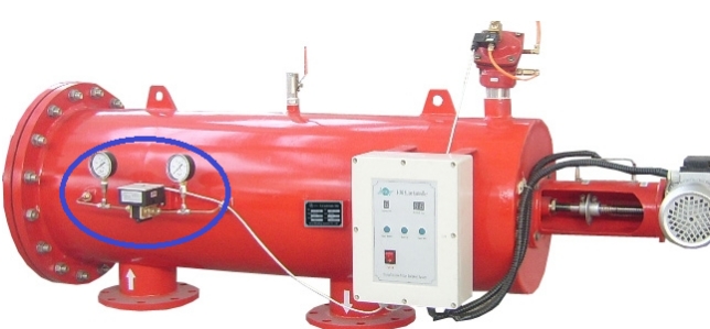
Differential Pressure Switches for the Auto Backflush Filter
(Adjustable D-P Switch, GE-511 series, made by A.YITE TECH)
Calibration steps for set points to reduce differential pressure:
Step 1
Connect the continuity test lamp or digital multimeter to the C- normal and NO- normally open contacts.
Step 2
Close the vent valve, open the balance valve, and raise the pressure on both sides of HI and LO to the normal working static pressure.
step 3
With normal HI pressure stable, close the balance valve to isolate the HI side from the LO side.
Step 4
Slightly open the discharge valve on the LO side to reduce the pressure on the LO side (increase the differential pressure) until a normal operating differential pressure appears on the differential pressure gauge. Close the discharge valve to stabilize the differential pressure. When the normal working differential pressure is reached, the contact should be closed (closed). If the contact is still disconnected under normal operating differential pressure, adjust the setting screw until the contact becomes loose.
Step 5
To keep the HI side pressure stable, open the balance valve slightly to increase the LO side pressure (reduce the differential pressure) until the desired differential pressure setting point appears on the differential pressure gauge.
Close the balance valve to stabilize the differential pressure. Check the state of the electrical contact under the following differential pressure and follow the instructions that match the state of the contact:
(a) set the point to "normal" if:
The contact moves precisely when the differential pressure setting value decreases, repeating the steps
Verify 2-5 as required to verify calibration. Calibration completed.
(b) contact open - the set point is too high
If the contact opens when a reduced differential pressure is achieved, adjust the setpoint screw until the contact closes. From this point, adjust the set point screw again until the contact disconnects. Repeat steps 2-5
(c) contact closure -- the set point is too low