User Manual For Explosion Proof Adjustable Flow Switches
1、 Product introduction
Ge-325 is an explosion-proof flow switch designed and manufactured by Hong Kong Aite company based on the principle of thermal diffusion. The flow switch converts the temperature difference signal into the corresponding electrical signal, so as to display and control the medium flow. It adopts cast aluminum explosion-proof shell, with explosion-proof level up to exdiict6 and explosion-proof certificate.
2、 Product advantages:
The flow probe and the signal processor of the thermal conductivity flow switch are integrated, so the anti pollution ability is stronger;
LCD liquid crystal displays the media flow in percentage form in real time;
The switch action value can be adjusted by pressing the key;
Optional output form of transistor or relay.
3、 Technical parameters
Measurement range: water: 3-300cm / S; gas: 200-3000cm / S; oil: 3-300cm / S
Switch accuracy: ± 1 - ± 10cm / S
Preheating time: within 1 minute after power on, the normal display is 8888
Working pressure: 100bar
Medium temperature: - 20 ℃ - 80 ℃
Process connection: G1 / 2, G1 "(other customizable)
Output signal: relay (SPDT)
Contact capacity: 30VDC / 3a, 110VAC / 3a, 250VAC / 3A
Power supply: 18-32vdc
Sensor length: 50mm (standard), other length optional
Display: 4-bit led liquid crystal display, 0-100%
Consumption current: < 100mA
Response time: 1-10S, typical value: 2S
Medium temperature change rate: ≤ 15 ℃ / min
Electrical protection: reverse / overload / short circuit
Protection grade: IP67
Electrical connection: M20X1.5
Probe material: 304SS, 3161 optional
Body material: Die Cast Aluminum
Explosion proof adjustable flow switch
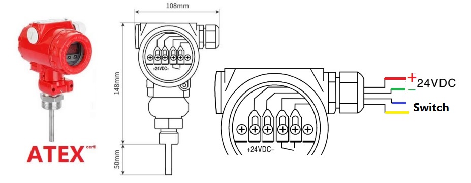
4、 Connection of wires
Please use explosion-proof cable, or take off the waterproof gland and refit the explosion-proof threading pipe. Please wire according to the following figure
5、 Connection to pipes
*The joint thread shall be suitable. Confirm the joint size before installation to avoid damage to the product.
*During installation, pay attention to the protection of the wiring plug and the bottom probe, and completely avoid any strong collision and injury.
*After installation, ensure that there is no leakage and other abnormal conditions at the joint.
*Use proper tools when tightening the flow switch, so as to avoid product damage and looseness.
*It should be ensured that most of the sensor probe can sense the flow of water, for example, it can be installed in the middle of the vertical upward pipeline or the side of the horizontal pipeline
6: Adjustment of flow switch and product regulation
6.1 function description of control key
The description of the control keys from left to right are: set key, forward key and backward key. Their functions are as follows:
Set: the setting key is used for parameter selection, setting and entering the main menu from the working interface;
<: shift key, which is used for forward turning of parameters and forward cycling of data modification bits. When the pipeline water flow is in static state, when the display is zero below, long press this key to return to zero.
Up key: used for parameter abandonment, back flip and data bit increment.
6.2 parameter function description
Alon: alarm start value factory default 45% (when the flow value is greater than 45% of the maximum flow, the switch is on)
Alof: alarm stop value factory default 40% (when the flow value is less than 40% of the maximum flow, the switch is off)
6.3 debugging
When leaving the factory, the flow switch has been debugged, which can meet the use requirements of general working conditions. It does not need to be debugged again by the site personnel. Under special working conditions, the flow switch can be calibrated according to the site working conditions. The method is as follows:
A. Install the flow switch, open the valve, and close the pump and fire hydrant to ensure that the pipe is full of water and does not flow.
B. Turn on the power and the flow switch will warm up, during which 8888 will be displayed all the time.
C. After 1min, the flow switch displays the flow percentage normally, so the following settings can be made:
1) If the water flow static state display is not zero, it can be reset to zero by long pressing the middle shift key < 3 seconds.
2) If the water flow static state display value is more than 30%, long press the shift key does not work, and at the same time press the set + < key to display pass, Press the up key to display 000 and the shift key to input 110, press the set key until ad is displayed, then press the up key to display the zero value, press the shift key once to save the zero value, then open the valve, after the water flows at the highest speed, press the up key to save the full value, then press the set key to exit the setting and enter the detection state.
7、 Precautions
7.1 when the flow switch is stored, moved or installed, it is not allowed to fall, to prevent falling, so as to avoid damage to the flow switch.
7.2 please make sure that the wiring is correct according to the requirements in the manual before connecting the power supply. When connecting the power supply, please check whether the power supply voltage of the flow switch is consistent with the product mark before connecting again to prevent the flow switch from being burnt out by the wrong power supply.
7.3 lay signal cables at a safe distance from high-voltage and high-frequency equipment and cables, so as to avoid interference to output signals of flow switch and damage of flow switch caused by induced high voltage.
 ∷
∷